Building a Secure Boot Chain on the STM32F411 (Part 2): Validation, Hidden Triggers, and Reverse Engineering
Author: Shafeeque Olassery Kunnikkal | Category: IoT, IoT Security, STM32F411 | Leave a Comment
This post is part of my STM32F411 Secure Boot Lab series, a hands-on embedded security project built around a Black Pill board, a compact cryptographic bootloader, and a reusable firmware analysis workflow. Across the series, I cover authenticated boot, fail-closed validation, hidden trigger engineering, and reverse engineering preparation in Ghidra.
Series page: STM32F411 Secure Boot Lab series
Project repository: This lab is part of my IoT_Projects GitHub repository, where I collect IoT, embedded security, and firmware research projects.
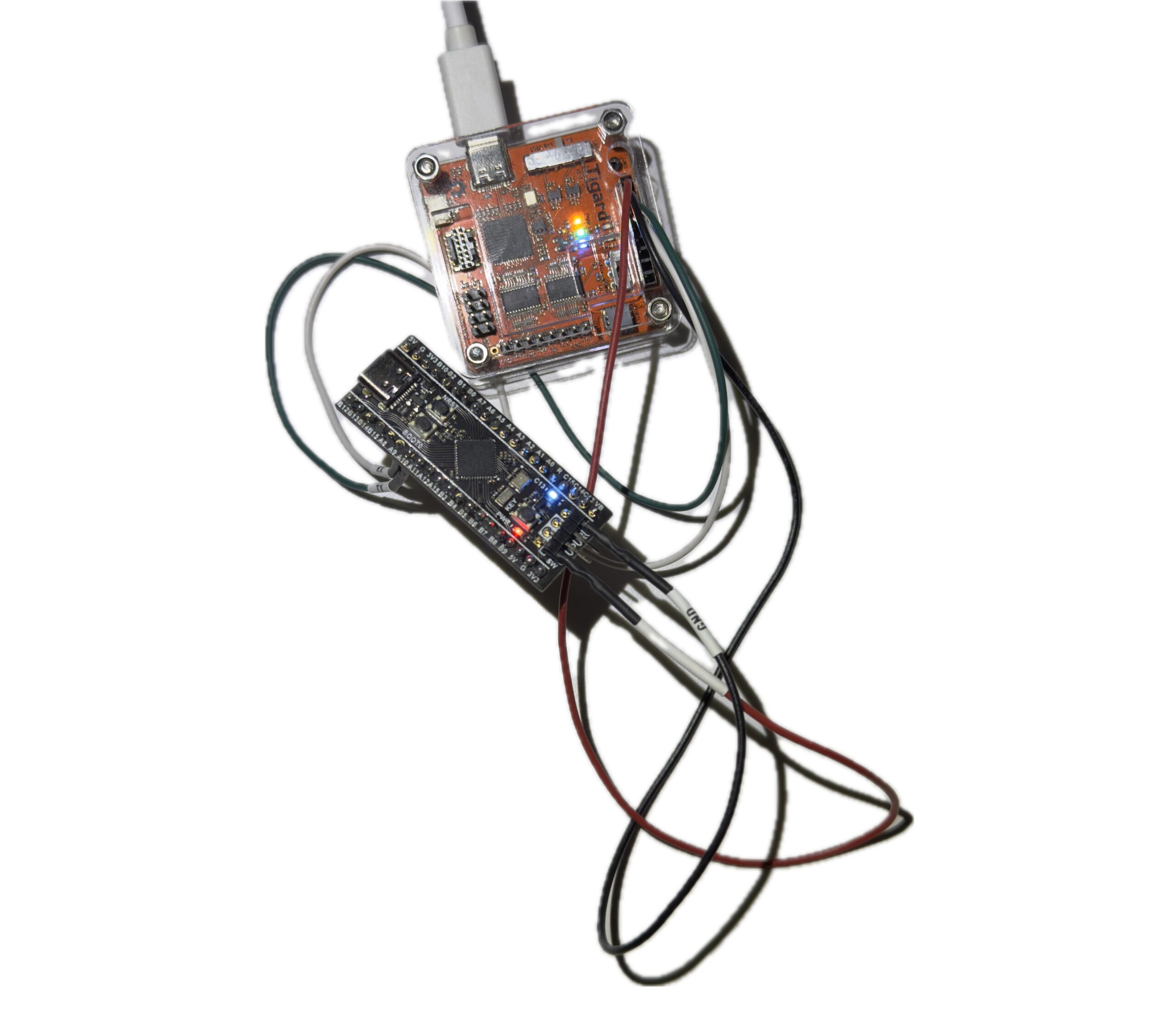
Part 1 of this project ended with a major milestone: a working secure boot chain on the STM32F411CEU6 Black Pill. The bootloader validated the image header, checked the application vectors, verified the SHA-256 and ECDSA-P256 signature path, and cleanly jumped to the diagnostic application.
That was a satisfying result, but it was not the end of the work.
A secure boot lab becomes far more useful once it moves beyond the happy path. It is one thing to show that valid, signed firmware boots. It is another to show, through controlled testing, that malformed, modified, or otherwise untrusted firmware does not.
In this second phase, I shifted from implementation to validation. I wanted to pressure-test the fail-closed behavior of the boot chain, finalize an interrupt-driven hidden trigger inside the payload, and shape the platform into a realistic target for binary diffing and reverse engineering in Ghidra.
Because in embedded security, a working demo is only half the story. The other half is whether the system rejects bad input in the right places, for the right reasons, and in a way that can be analyzed later.
Why Validation Matters
In security engineering, success cases are not enough.
A bootloader that accepts valid firmware is useful, but only partially convincing. A trust chain becomes more meaningful when it predictably rejects invalid firmware. Validation has to answer the harder questions. What happens if a single byte changes in the packed image? What happens if the signature metadata is malformed? What happens if the image is flashed to the right location but no longer matches the embedded public key?
The first major validation task for this phase was deliberately simple: modify the packed firmware and confirm that the bootloader refused to continue.
By flashing an image with an intentionally corrupted signature, I was able to observe the bootloader fail closed and prevent the application from running. That matters because it moves the project from “the good path works” to “the bad path is enforced.”
Defining and documenting these rejection cases is what starts turning a working implementation into a real security boundary.
Engineering the Payload: An Interrupt-Driven Hidden Trigger
To make the lab more realistic as an analysis target, the application running behind the secure bootloader needed to be more than a blinking LED and a visible console. It needed a hidden behavior that could later be hunted down from the compiled binary.
So I introduced an intentional trigger into the application’s UART path.
While the main loop continues printing its regular output, a hardware interrupt in USART1_IRQHandler listens to the RX buffer in the background. If it sees the exact six-byte sequence REBOOT, it sets a volatile flag and causes the main loop to call NVIC_SystemReset().
This was not added as a stealth feature for deployment. It was added as a controlled lab artifact: something small, intentional, and useful for later reverse engineering.
Getting that UART RX path working exposed a classic embedded systems issue.
At one stage, the application would boot, print its success banner, and then appear to ignore UART input completely. The problem was not the payload logic itself. The problem was inherited CPU state.
Right before handing execution over to the application, the secure bootloader disables interrupts globally with __disable_irq(). That is a sensible step during the jump, but the application inherits that state. In other words, the payload started life with interrupts still disabled.
The fix was simple once the root cause was clear: explicitly call __enable_irq() at the start of the application’s main() function.
Once I made that change, the interrupt-driven trigger behaved as expected.
This was a useful lesson because it had nothing to do with cryptography and everything to do with real boot-chain behavior. In embedded work, the handoff between stages includes CPU state, not just memory addresses.
Preparing for Reverse Engineering in Ghidra
One reason I like this project as a longer-term platform is that it naturally produces good reverse engineering targets.
With this payload in place, I am no longer only the developer. I am also creating a sandbox for the analyst.
The compiled application binary can be imported directly into Ghidra as a raw Cortex-M image. Once the binary is mapped at the correct base address, 0x08008200, the higher-level C code disappears and the reverse engineering problem becomes much more interesting.
The intentionally introduced REBOOT trigger becomes a clear hunting point. A researcher can search for the string, follow cross-references, locate the comparison logic, and then trace how it reaches the flag that ultimately triggers a reset.
That makes the binary useful as more than just a compiled firmware blob. It becomes a controlled challenge.
This is also where binary diffing becomes valuable. A clean baseline application and a deliberately modified version create an ideal comparison pair. That makes it possible to study exactly how a behavioral change appears at the binary level, both in raw diffing and in Ghidra’s disassembly and decompiler views.
For me, that is one of the biggest benefits of this lab. It is not just a secure boot demonstration. It is also a bridge into firmware RE workflow.
The Hardening Roadmap
With the software trust chain behaving as expected, the next logical layer is hardware hardening.
For the STM32 platform, the most obvious candidates are Write Protection (WRP) and Read-Out Protection (RDP). Secure boot ensures that only trusted code executes. RDP helps prevent an attacker from trivially attaching a debugger and extracting firmware or other useful material directly from flash.
I see that as the logical next phase.
There is value in first validating that the software trust chain behaves the way I expect. Once that foundation is solid, adding hardware-backed controls will push the platform beyond a secure boot demo and closer to a more complete defensive research lab.
That is also where the project gets more interesting from a security perspective. The conversation shifts from “can I verify code before boot?” to “how difficult is it to tamper with, extract, analyze, or bypass this platform in practice?”
Conclusion
This second phase of the STM32F411 secure boot lab was less about building and more about validating.
The happy path was already established. The real work in this phase was proving that failure cases fail safely, debugging the interrupt-driven UART trigger, and shaping the resulting firmware into something that can be analyzed through binary diffing and reverse engineering.
That shift matters.
In embedded security, confidence comes from careful validation, clear failure handling, and an honest understanding of what has and has not yet been proven. For me, this phase marks the transition from a working secure boot demo to a more defensible and reusable embedded security lab.
A secure boot chain is only convincing once it proves not just that valid firmware boots, but that invalid firmware does not.
Start from the beginning: Part 1 — Building a Compact Cryptographic Secure Boot Chain on STM32F411: My First AI-Co-Authored Embedded Security Lab
Series page: STM32F411 Secure Boot Lab Series