Building a Compact Cryptographic Secure Boot Chain on STM32F411
Author: Shafeeque Olassery Kunnikkal | Category: IoT, IoT Security, STM32F411 | Leave a Comment
This post is part of my STM32F411 Secure Boot Lab series, a hands-on embedded security project built around a Black Pill board, a compact cryptographic bootloader, and a reusable firmware analysis workflow covering authenticated boot, fail-closed validation, hidden trigger engineering, and reverse engineering preparation.
Project repository: This lab is part of my IoT_Projects GitHub repository, where I collect IoT, embedded security, and firmware research projects.
Most embedded projects are built around a simple assumption: if the board powers on and the firmware runs, the system is fine.
For embedded security, that assumption is not enough.
If a device will boot any image placed in flash, then firmware integrity and authenticity are largely being taken on faith. I wanted to build something better: a small STM32-based lab that would only boot an application if that application was well-formed, correctly placed, and cryptographically signed.
That became this project.
In this lab, I built a compact secure boot chain on the STM32F411CEU6 Black Pill using STM32CubeIDE, SHA-256, and ECDSA-P256. The bootloader validates the image header, checks the application vectors, hashes the application image, verifies the signature, and only then jumps to the application. If anything is wrong, it fails closed.
I chose this as my serious embedded security pilot because it is small enough to complete on inexpensive hardware, but rich enough to expose the kinds of problems that matter in real firmware work: flash layout, linker behavior, VTOR relocation, control transfer, and crypto integration on a microcontroller.
By the end of the project, the secure boot chain was working end to end.
Why I Started Here
I did not want my IoT or embedded security project to be flashy but shallow.
I wanted something that solved a real problem, forced me to deal with practical constraints, and could serve as a base for later work. Secure boot checked all three boxes.
At a high level, firmware trust sits underneath many other security claims. If a system cannot verify what it is about to execute, then update security, platform integrity, and even later reverse engineering exercises become less meaningful.
That is why I picked this use case.
I also chose the STM32F411CEU6 Black Pill very deliberately. It is affordable, widely available, well supported in STM32CubeIDE, and capable enough to run a compact public-key verification flow without making the project unreasonably heavy for this lab.
This was never meant to be a one-off demo. I wanted signed binaries, a clean bootloader/application split, visible UART evidence, and a structure I could reuse later for tamper tests, binary diffing, Ghidra work, and hardening experiments.
Project Goal
The goal was to implement a fail-closed secure boot chain on the STM32F411CEU6 Black Pill.
- validate the image header
- validate the application vector table
- compute SHA-256 over the application image
- verify an ECDSA-P256 signature
- jump only if all checks passed
- fail closed on invalid header, invalid vectors, invalid signature, or malformed image layout
I also wanted the application itself to be visible and testable. Instead of a hidden payload, I built a diagnostic app with UART output and LED behavior so I could confirm that the boot chain was really working.
Lab Environment
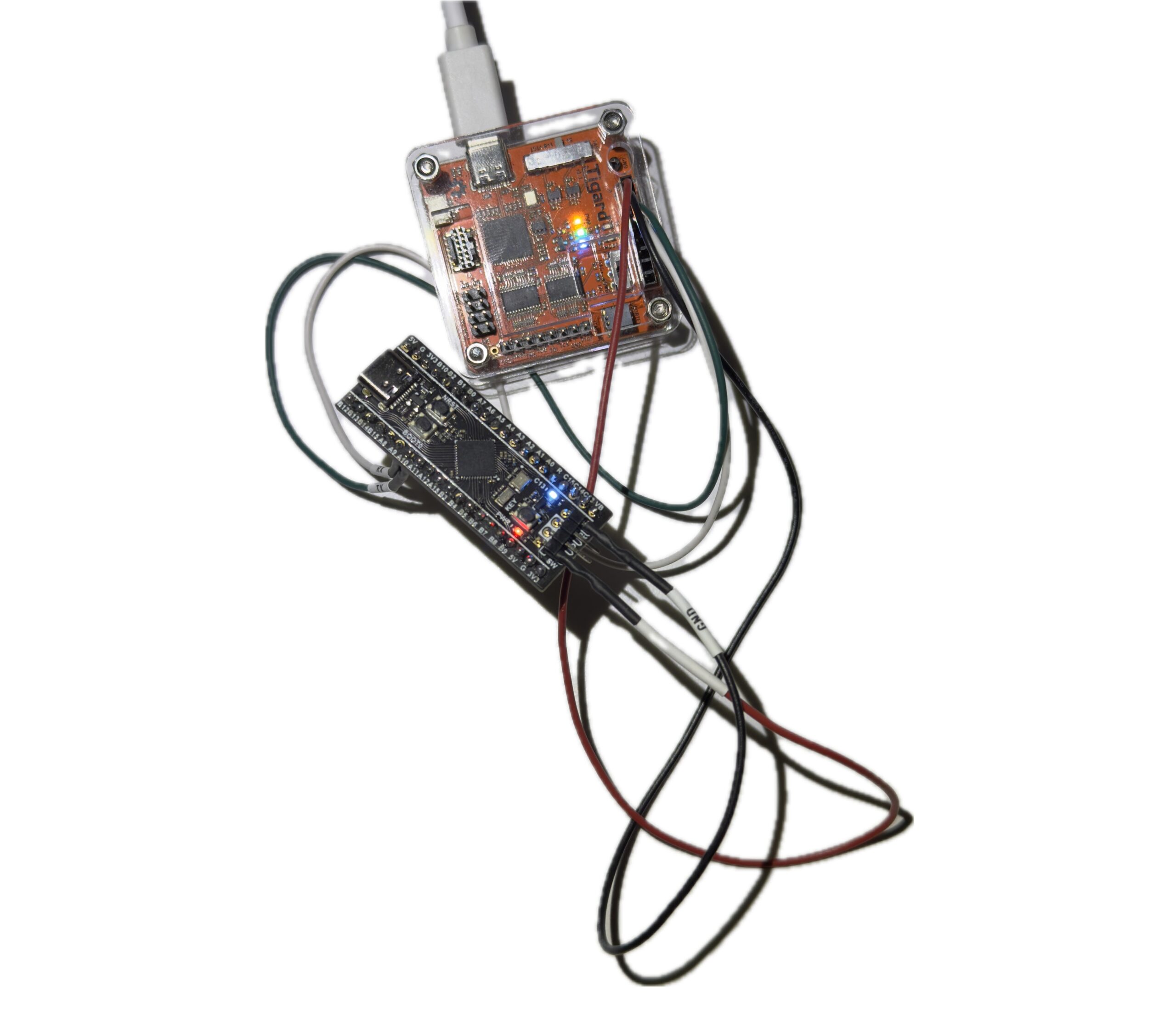
Hardware Used
- STM32F411CEU6 Black Pill V2.0
- ST-Link V2
- Tigard / FTDI dual-channel UART adapter
Software Used
- STM32CubeIDE
- OpenSSL
- ST-packaged Mbed TLS
- Python helper scripts for packing and key conversion
I intentionally kept the setup simple and practical. I wanted a workflow that felt close to real embedded development rather than a heavily abstracted demo.
Final Memory Map
The final working flash layout was:
- Bootloader:
0x08000000 .. 0x08007FFF(32 KB) - Image header:
0x08008000 .. 0x080081FF(512 bytes) - Application vectors + code:
0x08008200and above
This layout made the trust boundaries very clear.
The bootloader lives in a fixed region. The signed header sits at a known address. The application vector table begins immediately after the header, followed by the rest of the application code.
That separation made the rest of the project easier to reason about, especially the linker configuration, vector checks, and host-side packing flow.
Bootloader Design
The bootloader project was named Project_1_1_Bootloader.
Its job was intentionally narrow:
- validate the image header
- validate the app vectors
- calculate SHA-256 over the app image
- verify the ECDSA-P256 signature using an embedded public key
- jump to the app if valid
- fail closed otherwise
That simplicity was a design choice. For secure boot, small and predictable is better than complicated.
Important Bootloader Files
mbedtls_config_boot.himage_header.hverify.c- updated
main.c pack_image.pypublic_key_to_c.py
Mbed TLS Source Files Required
For the ST-packaged Mbed TLS copy I used, the minimum working set ended up being:
bignum.cbignum_core.cconstant_time.cecp.cecp_curves.cecdsa.csha256.cplatform_util.c
One useful lesson here was that bignum.c alone was not enough. Because of the way the ST package was structured, I also had to add bignum_core.c and constant_time.c to resolve missing mbedtls_ct_* and mbedtls_mpi_core_* linker symbols.
Bootloader Size
text = 22136
data = 92
bss  = 1980
That kept total flash use at about 22.2 KB, safely inside the 32 KB bootloader region.
Application Design
The application project was named Project_1_2_App.
Its purpose was not stealth. Its purpose was observability.
The app was linked to run from 0x08008200 and included:
- USART1 diagnostic console
- LED heartbeat on PC13
- simple commands:
STATUSVERSIONLEDONLEDOFF
Application Configuration
- USART1 on
PA9 / PA10 - PC13 LED
115200 8N1- VTOR relocation enabled
- linked in flash, not RAM
Important Linker Fix
One of the early app failures came from the linker script behaving like a debug-in-RAM configuration. That placed vectors and code in RAM, which made the image invalid for this boot flow.
The corrected section behavior was:
.isr_vector -> FLASH.text -> FLASH.rodata -> FLASH.data -> RAMwithAT > FLASH.bss -> RAM
VTOR Relocation
In system_stm32f4xx.c, the app uses:
#define USER_VECT_TAB_ADDRESS
#define VECT_TAB_OFFSET  0x00008200U
That relocation is required so the application uses its own vector table after the bootloader jumps to it.
Key Generation and Signing Workflow
The signing workflow was kept simple and repeatable.
First, I generated the keypair on the host:
private.pempublic.der
Then I converted the public key into a C array using public_key_to_c.py and embedded it into the bootloader verification code.
The application was built as a raw .bin, then packed and signed with:
python3 pack_image.py Project_1_2_App.bin app_packed.bin --key private.pem --version 1This produced a packed image where:
- the 512-byte signed header is written at
0x08008000 - the application vectors and code start at
0x08008200
Flash Order
- Flash
Bootloader.elfto0x08000000 - Flash
app_packed.binto0x08008000
That separation felt clean and correct. The PC signs the image. The MCU verifies it.
The Most Important Bug
The most important runtime problem was not in the application and not in flashing.
It was in the bootloader’s vector sanity check.
At one point, the bootloader kept printing:
[boot] invalid vectors
[boot] fail closed
That was confusing because the image header looked correct and the app vectors at 0x08008200 also looked valid.
A memory inspection showed:
SP = 0x20020000Reset = 0x08008AF5
Those values were valid, but the bootloader still refused to continue.
Root Cause
The original stack pointer check used this logic:
if ((sp & 0x2FFE0000UL) != 0x20000000UL) return 0;That rejected 0x20020000, even though it is a valid top-of-RAM initial MSP value for the STM32F411.
Fix
I replaced that brittle bitmask test with a proper range check:
if (sp < 0x20000000UL || sp > 0x20020000UL) return 0;
if ((sp & 0x3U) != 0U) return 0;
if ((rv & 1U) == 0U) return 0;
if ((rv & ~1U) < APP_VECTOR_ADDR || (rv & ~1U) >= FLASH_END_ADDR) return 0;
As soon as I made that change, secure boot worked.
This was a very useful lesson. In embedded security, a trust chain can fail even when the cryptography is correct. Low-level validation logic still has to be right.
Hardware and UART Notes
ST-Link Wiring
SWDIO -> DIOSWCLK -> SCKGND -> GND3.3Vonly if intentionally powering from ST-Link
UART Wiring
- board
PA9 / USART1_TX -> adapter RX - board
PA10 / USART1_RX -> adapter TX GND -> GND
On Kali Linux, the FTDI/Tigard adapter appeared as:
/dev/ttyUSB0/dev/ttyUSB1
The correct console output was on:
/dev/ttyUSB0
Picocom Command
picocom -b 115200 /dev/ttyUSB0or:
picocom -b 115200 --echo /dev/ttyUSB0At the end of the session, application TX was confirmed working, but the command RX path still needed final validation. The command code exists, but interactive RX did not respond in the terminal during the last session.
The most likely remaining issue is UART RX wiring, FTDI channel selection, or final interrupt-path validation. This does not block the secure boot result, but it is the next thing to finish.
Final Result
The secure boot chain worked.
The bootloader successfully verified the signed application and jumped to it. The known-good UART output was:
[boot] secure boot starting
[boot] signature valid

=================================
[app] Application Boot Successful
[app] Diagnostic Console Enabled
Commands: STATUS, VERSION, LEDON, LEDOFF
=================================
[app] tick...
That output confirms several important things at once:
- the bootloader is running
- the header is valid
- signature verification succeeds
- the app vectors are acceptable
- the jump to the application works
- the application runtime is alive
That made this an end-to-end success, not just a cryptographic unit test.
What This Lab Taught Me
A few takeaways stood out.
First, memory layout is part of the security model. Flash addresses, linker behavior, and vector placement are not background details in a secure boot design.
Second, embedded crypto is practical, but integration still matters. Even a minimal library setup can involve missing pieces and linker surprises.
Third, a valid signature path is not enough by itself. Startup assumptions, vector checks, and jump conditions can make or break the trust chain.
And finally, visible diagnostics are worth it. A UART-speaking test app with an LED heartbeat is far more useful in an early lab than a silent payload.
Next Steps
There are several obvious follow-up tasks for this lab:
- finalize the UART RX command path
- tamper with the packed image and confirm signature failure
- enable WRP
- test RDP Level 1
- create a clean app and a modified app for binary diffing
- use the resulting binaries in Ghidra
- explore secure boot bypass ideas from a defensive research angle
That is exactly why this project matters to me. It is not just a finished lab. It is a strong base for the next labs.
Conclusion
This project achieved its main goal: I built a compact cryptographic secure boot chain on the STM32F411CEU6 Black Pill that validates image structure, checks application vectors, computes a SHA-256 hash over the application, verifies an ECDSA-P256 signature, and transfers execution only when all checks pass.
If the image is invalid, it fails closed.
Just as importantly, the project forced me through the details that make embedded security real: flash layout, linker fixes, vector validation, boot-time assumptions, and practical crypto integration on a constrained MCU.
So while this article covers a single lab, I see it as the foundation for a larger embedded security track. It already supports tamper testing, binary comparison, reverse engineering, and future hardening work.
That makes it a strong pilot project and a useful platform for what comes next.
A secure boot chain is not just cryptography. It is memory layout, vector sanity, linker discipline, and a refusal to run code that has not earned trust.
Continue the series: Part 2 — Building a Secure Boot Chain on the STM32F411 (Part 2): Validation, Hidden Triggers, and Reverse Engineering
Series page: STM32F411 Secure Boot Lab Series